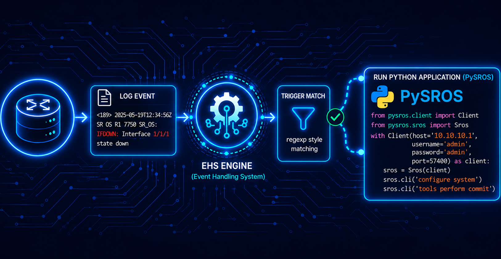
Understanding Flex Algo in Segment Routing Networks : Delay-Based Traffic Engineering
Flex-Algo on Nokia SR OS

Introduction and Architectural Motivation
Traditional Interior Gateway Protocols (IGPs), such as IS-IS and OSPF, compute forwarding paths using Dijkstra's Shortest Path First (SPF) algorithm based on a standard IGP link cost. This default routing paradigm is designated as Algorithm 0 and optimizes purely for cumulative IGP distance.
Modern service provider, 5G, and enterprise networks carry diverse traffic classes with strict Service Level Agreements (SLAs), including ultra-low latency, strict geographical constraints, link bandwidth affinity, and physical path disjointness.
Historically, operators engineered constraint-based paths using RSVP-TE (Resource Reservation Protocol with Traffic Engineering) or Segment Routing Traffic Engineering (SR-TE) driven by Path Computation Elements (PCE). These mechanisms carry operational overhead :
- RSVP-TE introduces signaling states on every transit node along the label-switched path, creating scalability constraints
- SR-TE with centralized PCE requires path computation engines, BGP-LS, PCEP signaling, and often results in deep Segment Identifier (SID) label stacks that risk exceeding hardware Maximum SID Depths (MSD)
Flexible Algorithm (or Flex-Algo) provides a mechanism for IGPs to compute constraint-based paths across a domain using extensions to IS-IS and OSPF to advertise TLVs containing one or more Flexible Algorithm Definitions (FAD). Each FAD is associated with a numeric identifier and identifies a set of metrics and constraints that should be used to calculate the best path along the constrained topology.
The Goal of Flexible Algorithms
Using Flexible Algorithms is a simple way to achieve traffic engineering for simple use-case scenarios
- Optimum paths can be calculated using a different metric, including IGP cost, TE cost, or link delay
- Separate network topologies can be created and reserved to be used by different applications
- The advantage of Flex-Algo is that there is no need to configure individual LSPs, each with its own set of TE constraints
- SR tunnels will be automatically created by the routing protocol between every pair of routers participating in a given Flex-Algo instance
- An additional advantage of Flex-Algo is that a single MPLS label is enough to represent each TE-constrained path, contrary to SR-TE, which typically requires multiple labels
How Flexible Algorithms work
- The Flexible Algorithm Definition (FAD) is the construct that identifies how a path for a particular Flex-Algorithm should be computed, and consists of three components, namely calculation-type, metric-type, and a set of constraints, such as include or exclude statements
- Advertise once, participate everywhere. Only some routers need to advertise the FAD, but every router in the topology must be configured to participate. A router without Flex-Algo on Nokia SR OS does not participate and ignores the FAD for that algorithm.
- A Node-SID per algorithm. The egress router advertises one Prefix Node-SID for algorithm 0 and another for the Flex-Algo. The ingress router selects the algorithm simply by choosing which label it pushes.
- Application-specific link attributes (ASLA) allow for multiple sets of link attributes to be advertised for a given link, and also to independently associate a set of link attributes
- Constraints with admin groups. Links can carry admin groups, which work like colors. A FAD can
excludelinks that carry a group,include-anyto keep only links that carry at least one of a set of groups, orinclude-allto keep only links that carry every group in a set. Links that fail the test are pruned from that algorithm's topology.
Two rules catch people out*. When a FAD selects a metric type, only links that have that metric type configured are included in the Flex-Algo topology, so a link with no delay value is silently pruned from a delay-based algorithm. And the constraint lives in the FAD: tagging a link with an admin group does nothing until a FAD that references the group is advertised and in use.*
The Lab
Six SR OS nodes running release 24.10.R5, one IS-IS level, SR-MPLS.
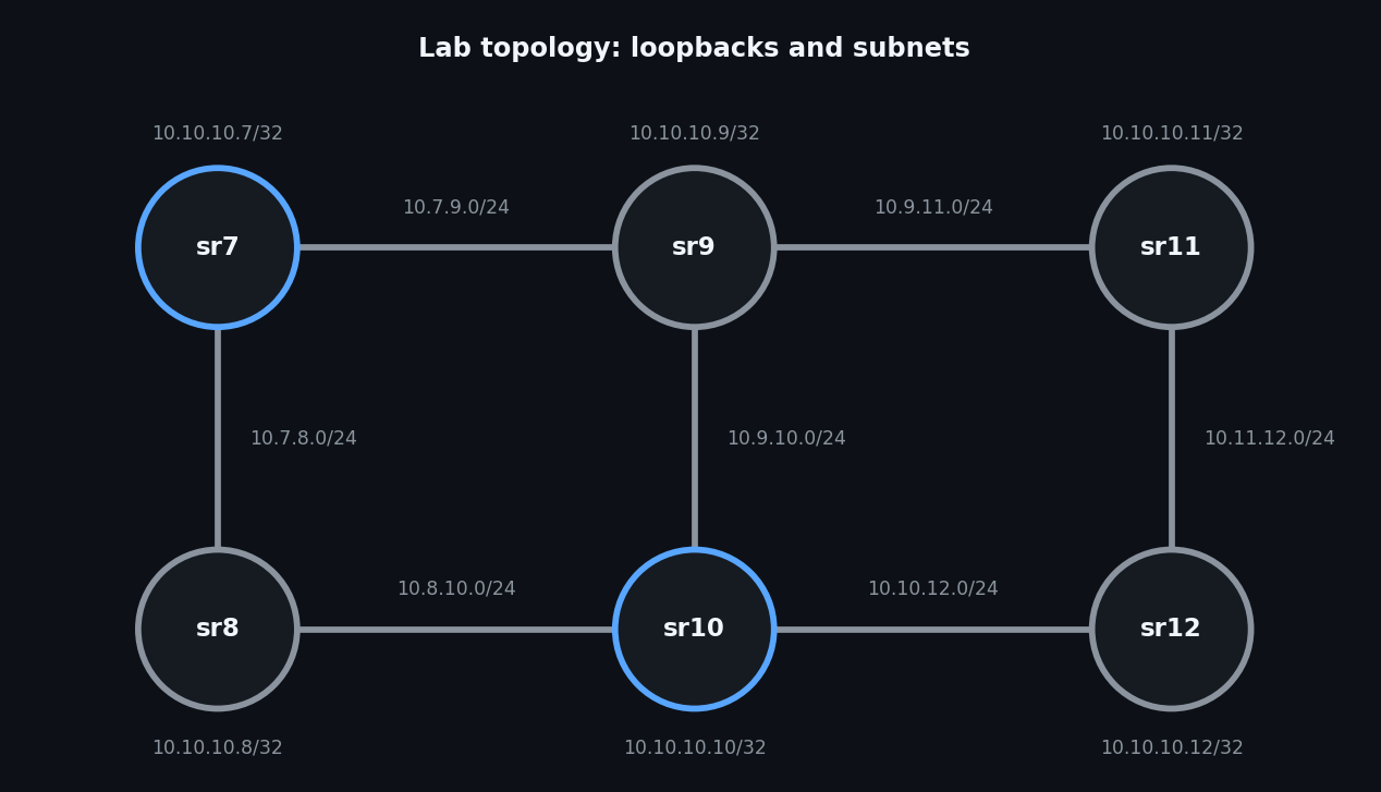
The goal is an SR LSP from sr7 to sr10 (10.10.10.10) that follows the lowest delay.
Part 1: Measure link delay with TWAMP-light
Flex-Algo needs a delay value per link. It can be configured statically, but here it comes from link measurement, which sends TWAMP-light (STAMP) probes over each IP interface and reports the result to the routing engine.
How the measurement works
- A measurement template defines the test: probe interval, which delay metric to compare (minimum, maximum or average), and the measurement windows and thresholds.
- Probes are grouped into a sample window (the interval multiplied by the window multiplier) and an aggregate sample window (several sample windows).
- At the end of a window, the result is compared with the thresholds (an absolute change in microseconds, or a relative percentage) against the delay last reported. If a threshold is reached, the new delay is reported to the routing engine and flooded in IS-IS. At least one threshold must be configured, or nothing is reported.
- The interface references the template and enables the probe protocol (IPv4 or IPv6). The peer needs a TWAMP-light reflector
unidirectional-measurement derivedcomputes the one-way delay as the round-trip time divided by two, andactualuses real timestamps and needs near-exact clock synchronisation. The values in this article assumederived
1.1 The measurement template
This is the template used in the lab, applied on every router:
configure {
    test-oam {
        link-measurement {
            measurement-template "my-probe" {
                admin-state enable
                delay avg
                interval 10
                aggregate-sample-window {
                    multiplier 10
                    window-integrity 10
                }
                sample-window {
                    window-integrity 10
                    threshold {
                        relative 100
                        absolute 2000
                    }
                }
            }
        }
    }
}
The thresholds sit on the sample window, so a change of 2000 microseconds (2 ms) or more, or a 100 percent change, is reported when a sample window completes.
1.2 The reflector
Each router answers probes from its neighbours:
configure {
    router "Base" {
        twamp-light {
            reflector {
                admin-state enable
                udp-port <port that matches the template's dest-udp-port>
            }
        }
    }
}
The session-sender and session-reflector must agree on the UDP port. The reflector may also need a prefix or source list, so check configure router "Base" twamp-light reflector ? on your release.
1.3 Attach the template to each interface
On sr7, interface to-sr9:
configure {
    router "Base" {
        interface "to-sr9" {
            if-attribute {
                admin-group ["GREEN" "RED"]
                delay {
                    dynamic {
                        measurement-template "my-probe"
                        twamp-light {
                            ipv4 {
                                admin-state enable
                                destination 10.7.9.2
                            }
                        }
                   }
                }
            }
Two details matter here:
Destination address. With IPv4, the source is taken from the interface's primary address, and the destination is auto-assigned only when the prefix length is /30 or /31. These lab links are /24 subnets, so the destination must be configured explicitly, as above.
Every link, both ends. Delay is unidirectional, so configure each interface on both routers. Loopback and system interfaces do not support the test.
1.4 Verify the measurement
 show test-oam link-measurement interfaces

===============================================================================
Link Measurement Interface Operational Summary
===============================================================================
Interface
     Oper Protocol DetectableTxErr Report Monitor Delay(us)           Timestamp
-------------------------------------------------------------------------------
Interface: tosr9
       Up     IPv4            None    Yes     Avg      1182 2026/11/01 20:37:15
===============================================================================

 show test-oam link-measurement interface "tosr9" detail

===============================================================================
Interface Link Measurement Information - tosr9
===============================================================================
Template Name: my-probe
Oper State               : Up
Protocol                 : IPv4
Oper Source Address      : 10.7.9.1
Source Auto-Assigned     : Yes
Oper Destination Address : 10.7.9.2
Destination Auto-Assigned: No
In-Use Src UDP Port      : 49154
In-Use Dst UDP Port      : 862
STAMP Session Identifier : 1000
Failure Condition(s)     : None
Detectable Tx Error      : None

-------------------------------------------------------------------------------
Reporting
-------------------------------------------------------------------------------
Reporting Operational      : Yes
Delay Measure Last Reported: 1182us
Timestamp                  : 2026/11/01 20:37:15
Triggered By               : SampleThresholdAbsolute

-------------------------------------------------------------------------------

 show test-oam link-measurement measurement-template-using

===============================================================================
Measurement Templates
===============================================================================
Template Name
 Interface Name                                                        Protocol
-------------------------------------------------------------------------------
my-probe
 tosr9                                                                     IPv4
===============================================================================
Look for: the test operationally up, protocol IPv4, no detectable transmission errors, and a last reported delay that is close to your target (the netem value plus a little real latency). The measured value is also available as telemetry: state test-oam link-measurement router interface last-reported-delay, with on-change notifications, so you can stream it with gNMI.
Part 2: Enable Flex-Algo
2.1 Enable ASLAs (all routers)
configure {
    router "Base" {
        isis 0 {
            traffic-engineering-options {
                application-link-attributes {
                }
            }
        }
    }
}
2.2 Define the admin group (all routers)
The admin group is defined once per router as an if-attribute in the routing options. Values run from 0 to 31:
configure {
    routing-options {
        if-attribute {
            admin-group "GREEN" {
                value 1
            }
             admin-group "RED" {
            value 2
           }
        }
    }
}
2.3 Flex-Algorithm Definition (FAD) and Participation
The first step is to define the Flex-Algorithm Definition (FAD) and advertise that FAD into the IGP, which in this example is IS-IS.
configure {
    routing-options {
        flexible-algorithm-definitions {
            flex-algo "Real-Time-Traffic" {
                admin-state enable
                metric-type delay
                include-all {
                    admin-group "GREEN" { }
                }
            }
        }
    }
    router "Base" {
        isis 0 {
            flexible-algorithms {
                admin-state enable
                flex-algo 129 {
                    participate true
                    advertise "Real-Time-Traffic"
                }
            }
        }
    }
}
The other routers only participate:
configure {
    router "Base" {
        isis 0 {
            flexible-algorithms {
                admin-state enable
                flex-algo 129 {
                    participate true
                }
            }
        }
    }
}
2.4 Assigning a Prefix Node-SID to a Flex-Algorithm
configure {
    router "Base" {
        isis 0 {
            interface "system" {
                ipv4-node-sid {
                    index 7
                }
                flex-algo 128 {
                    ipv4-node-sid {
                        index 207
                    }
                }
            }
        }
    }
}
2.5 Verify the control plane
On sr7:
show router isis database detail

===============================================================================
Rtr Base ISIS Instance 0 Database (detail)
===============================================================================

Displaying Level 1 database
-------------------------------------------------------------------------------
Level (1) LSP Count : 0

Displaying Level 2 database
-------------------------------------------------------------------------------
LSP ID    : sr7.00-00                                   Level     : L2
Sequence  : 0x141                  Checksum  : 0x4fea   Lifetime  : 1161
Version   : 1                      Pkt Type  : 20       Pkt Ver   : 1
Attributes: L1L2                   Max Area  : 3        Alloc Len : 1492
SYS ID    : 0100.1001.0007         SysID Len : 6        Used Len  : 363

TLVs :
  Area Addresses:
    Area Address : (2) 49.10
  Supp Protocols:
    Protocols     : IPv4
  IS-Hostname   : sr7
  Router ID   :
    Router ID   : 10.10.10.7
  Router Cap : 10.10.10.7, D:0, S:0
    TE Node Cap : B E M  P
    SR Cap: IPv4 MPLS-IPv6
       SRGB Base:100000, Range:1000
    SR Alg: metric based SPF, 129, 130

show router isis prefix-sids algo 129

===============================================================================
Rtr Base ISIS Instance 0 Prefix/SID Table
===============================================================================
Prefix                            SID        Lvl/Typ    SRMS   AdvRtr
                                   Shared     Algo       MT     Flags
-------------------------------------------------------------------------------
10.10.10.7/32                     207        2/Int.      N     sr7
                                      No         129        0      NnP
10.10.10.8/32                     208        2/Int.      N     sr8
                                      N.A.       129        0      NnP
10.10.10.9/32                     209        2/Int.      N     sr9
                                      N.A.       129        0      NnP
10.10.10.10/32                    210        2/Int.      N     sr10
                                      N.A.       129        0      NnP
10.10.10.11/32                    211        2/Int.      N     sr11
                                      N.A.       129        0      NnP
10.10.10.12/32                    212        2/Int.      N     sr12
                                      N.A.       129        0      NnP
-------------------------------------------------------------------------------
No. of Prefix/SIDs: 6 (6 unique)
-------------------------------------------------------------------------------

 show router tunnel-table 10.10.10.10/32 protocol isis

===============================================================================
IPv4 Tunnel Table (Router: Base)
===============================================================================
Destination           Owner     Encap TunnelId  Pref   Nexthop        Metric
   Color
-------------------------------------------------------------------------------
10.10.10.10/32 [L]    isis (0)  MPLS  524302    11     10.7.8.2       20
10.10.10.10/32        isis (0)  MPLS  524310    11     10.7.9.2       4304
-------------------------------------------------------------------------------

# Two tunnels to the same destination: one chosen by IGP cost (20) and one by delay (about 4 ms measured). Both use sr8 for now.
Part 3: Steer traffic with an SR Flex-Algo tunnel
There are several ways to steer traffic to be carried by flex-algo segment routing tunnels.
- In our case, we will use the Flex-Algo Node SID in a path definition of an SR-TE LSP
# Check the Flex-Algo Node SID

show router tunnel-table 10.10.10.10 detail

===============================================================================
Tunnel Table (Router: Base)
===============================================================================
Destination      : 10.10.10.10/32
NextHop          : 10.7.9.2
Tunnel Flags     : entropy-label-capable
Age              : 00h00m15s
CBF Classes      : (Not Specified)
Owner            : isis (0)             Encap            : MPLS
Algorithm        : 129
Tunnel ID        : 524310               Preference       : 11
Tunnel Label     : 100210               Tunnel Metric    : 3214
Tunnel MTU       : 9190                 Max Label Stack  : 2
-------------------------------------------------------------------------------

# Apply the Node-SID to a MPLS path

 }
    path "flex-algo" {
        admin-state enable
        hop 10 {
            sid-label 100210
        }
    }
  }
    lsp "tor10" {
        admin-state enable
        type p2p-sr-te
        from 10.10.10.7
        to 10.10.10.10
        primary "flex-algo" {
            admin-state enable
        }
    }

# Check the route the LSP takes

oam lsp-trace sr-te lsp-name "tor10"
lsp-trace to tor10: 1 hops min, 30 hops max, 104 byte packets
1  10.10.10.9  rtt=3.96ms rc=8(DSRtrMatchLabel) rsc=1
2  10.10.10.10  rtt=4.91ms rc=3(EgressRtr) rsc=1
Part 4: Containerlab netem
In Containerlab, the tools netem command suite allows you to inject real-world network impairments such as latency, jitter, packet loss, and rate-limiting directly onto any containerized node's interfaces.
We will utilize this tool to inject latency and to observe what happens to the Flexo-Algo tunnel, which has a TE constraint based on low delay.
It is available from Containerlab 0.44, so check containerlab version
Part 5: Demo
Step 1: healthy state
On sr7:
oam lsp-trace sr-te lsp-name "tor10" downstream-map-tlv ddmap
lsp-trace to tor10: 1 hops min, 30 hops max, 108 byte packets
1  10.10.10.9  rtt=1.63ms rc=8(DSRtrMatchLabel) rsc=1
2  10.10.10.10  rtt=3.06ms rc=3(EgressRtr) rsc=1
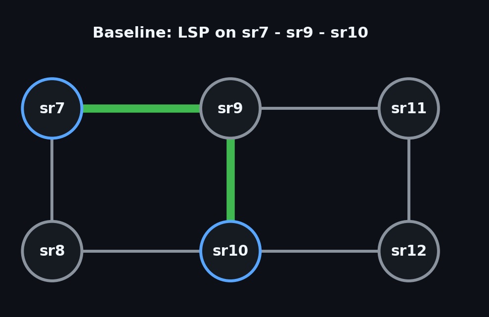
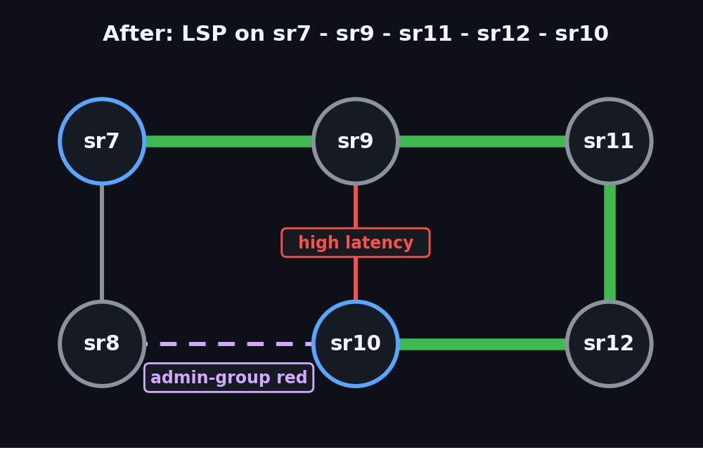
Step 2: degrade sr9 - sr10 and let TWAMP-light notice (the baseline)
Raise the sr9 - sr10 delay to 30 ms, on both ends:
containerlab tools netem set -n clab-segmentr_flex_algo-sr9  -i 1/1/2 --delay 30ms
╭──────────────┬───────┬────────┬─────────────┬─────────────┬────────────╮
│   Interface  │ Delay │ Jitter │ Packet Loss │ Rate (Kbit) │ Corruption │
├──────────────┼───────┼────────┼─────────────┼─────────────┼────────────┤
│ eth2 (1/1/2) │ 30ms  │ 0s     │ 0.00%       │ 0           │ 0.00%      │
╰──────────────┴───────┴────────┴─────────────┴─────────────┴────────────╯

 containerlab tools netem set -n clab-segmentr_flex_algo-sr10  -i 1/1/1 --delay 30ms
╭──────────────┬───────┬────────┬─────────────┬─────────────┬────────────╮
│   Interface  │ Delay │ Jitter │ Packet Loss │ Rate (Kbit) │ Corruption │
├──────────────┼───────┼────────┼─────────────┼─────────────┼────────────┤
│ eth1 (1/1/1) │ 30ms  │ 0s     │ 0.00%       │ 0           │ 0.00%      │
╰──────────────┴───────┴────────┴─────────────┴─────────────┴────────────╯
Confirm from sr9 that the round-trip time has risen to about 60 ms:
ping 10.9.10.2 count 5

PING 10.9.10.2 56 data bytes
64 bytes from 10.9.10.2: icmp_seq=1 ttl=64 time=63.2ms.
64 bytes from 10.9.10.2: icmp_seq=2 ttl=64 time=62.2ms.
64 bytes from 10.9.10.2: icmp_seq=3 ttl=64 time=62.1ms.
64 bytes from 10.9.10.2: icmp_seq=4 ttl=64 time=62.9ms.
64 bytes from 10.9.10.2: icmp_seq=5 ttl=64 time=62.6ms.

---- 10.9.10.2 PING Statistics ----
5 packets transmitted, 5 packets received, 0.00% packet loss
round-trip min = 62.1ms, avg = 62.6ms, max = 63.2ms, stddev = 0.387ms
This is the slow part, and it is the difference from a static delay. The new delay is reported only when a measurement window completes, a threshold is reached, and IS-IS then floods it and runs SPF.
Then on, sr7:
show router tunnel-table 10.10.10.10/32 protocol isis

===============================================================================
IPv4 Tunnel Table (Router: Base)
===============================================================================
Destination           Owner     Encap TunnelId  Pref   Nexthop        Metric
   Color
-------------------------------------------------------------------------------
10.10.10.10/32 [L]    isis (0)  MPLS  524302    11     10.7.8.2       20
10.10.10.10/32        isis (0)  MPLS  524310    11     10.7.9.2       3778
-------------------------------------------------------------------------------
Flags: B = BGP or MPLS backup hop available
       L = Loop-Free Alternate (LFA) hop available
       E = Inactive best-external BGP route
       k = RIB-API or Forwarding Policy backup hop
===============================================================================

oam lsp-trace sr-te lsp-name "tor10" downstream-map-tlv ddmap
lsp-trace to tor10: 1 hops min, 30 hops max, 108 byte packets
1  10.10.10.9  rtt=1.84ms rc=8(DSRtrMatchLabel) rsc=1
2  10.10.10.11  rtt=3.26ms rc=8(DSRtrMatchLabel) rsc=1
3  10.10.10.12  rtt=7.10ms rc=8(DSRtrMatchLabel) rsc=1
4  10.10.10.10  rtt=6.73ms rc=3(EgressRtr) rsc=1
The Flex-Algo SR tunnel changed automatically based on the lowest-delay path. Path is sr7->sr9->sr11->sr12->sr10
Conclusion
Flex-Algo gives you a delay-aware, policy-aware path with minimal configuration. The routers measure the links, compute the path, and move traffic when a link degrades automatically. For many networks, that is a good trade-off between objective and complexity
Comments
Join the discussionNo comments yet. Be the first to comment.